For electronics hobbyists, engineers, and other tech enthusiasts, understanding resistor color codes is essential. Resistors are common components in circuits and projects that help regulate voltage and current. The colored bands on the resistors contain numerical information for measuring resistance, but decoding their meaning can be a headache.
Fortunately, printable resistor color code charts provide a handy reference for deciphering even the most complex color codes. No longer do you need to memorize the value each color represents. With a chart on hand, looking up resistor values is quick and easy. In this guide, we provide free printable PDF and Word versions of color code charts for 4, 5, and 6 band resistors. Keep one near your workspace to eliminate the guesswork when reading resistor bands. Let’s explore how these charts work and how they can aid your electronics projects. With the right color code reference, you can work confidently knowing you’re using the correct resistor values.
Table of Contents
What Is a Resistor Color Code?
A resistor color code is a system used to indicate the values or ratings of electrical resistors. Resistors have colored stripes or bands on them, and each color represents a numeric value. The color code typically includes three or four bands of different colors to denote the resistance in ohms, tolerance percentage, and temperature coefficient. For example, a resistor with bands of yellow, violet, red, and gold would translate to 47 ohms with a 5% tolerance.
Resistor color codes allow technicians to quickly identify the properties of a resistor without having to measure them each time. The standardized color system eliminates confusion and mistakes when selecting and using resistors in circuits. Most commonly, 4-band color codes are used on resistors today to show the ohms, tolerance level, and reliability. Understanding resistor color codes through the use of charts and diagrams is essential for circuit design and analysis.
Printable Resistor Color Code Charts
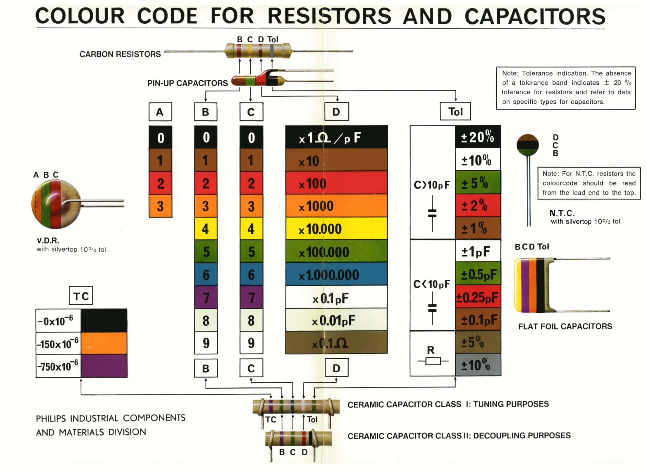
Resistors are common electrical components that reduce current flow. To determine the resistance value of a resistor, one must refer to the resistor color code chart. This chart correlates colors to numbers and is essential when reading the colored bands on a resistor.
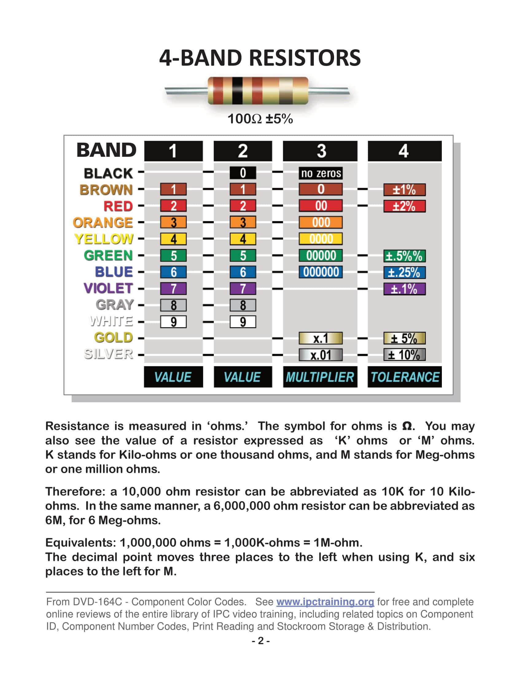
The resistor color code chart pdf is an indispensable tool for electronics hobbyists and professionals. The pdf chart provides the numeric values associated with each color band. For example, the first two bands represent the first two digits, while the third band is the multiplier. The fourth band denotes tolerance. Having this color to number correspondence in a pdf allows for easy reference when working with resistors.
The resistor color code chart pdf enables the user to accurately determine resistance given the colors present on a resistor. Whether learning about resistors for the first time or working with them daily, the color code chart pdf is a convenient resource to have available. Electronics enthusiasts can print the pdf and keep it at their workbench for fast access when the resistance of a resistor needs to be decoded. With simple color matching, the resistor value can quickly be identified.
Understanding the Resistor Color Code System
Resistors are essential components in electronic circuits, helping control the flow of electrical current. To indicate their resistance values, most resistors use a system of color bands. This system, known as the resistor color code, helps engineers and hobbyists quickly determine a resistor’s resistance value, tolerance, and sometimes its reliability.
Basic Color Code
Each color on a resistor represents a number. Here are the standard colors and their corresponding numbers:
- Black – 0
- Brown – 1
- Red – 2
- Orange – 3
- Yellow – 4
- Green – 5
- Blue – 6
- Violet (or Purple) – 7
- Gray – 8
- White – 9
Reading the Color Bands
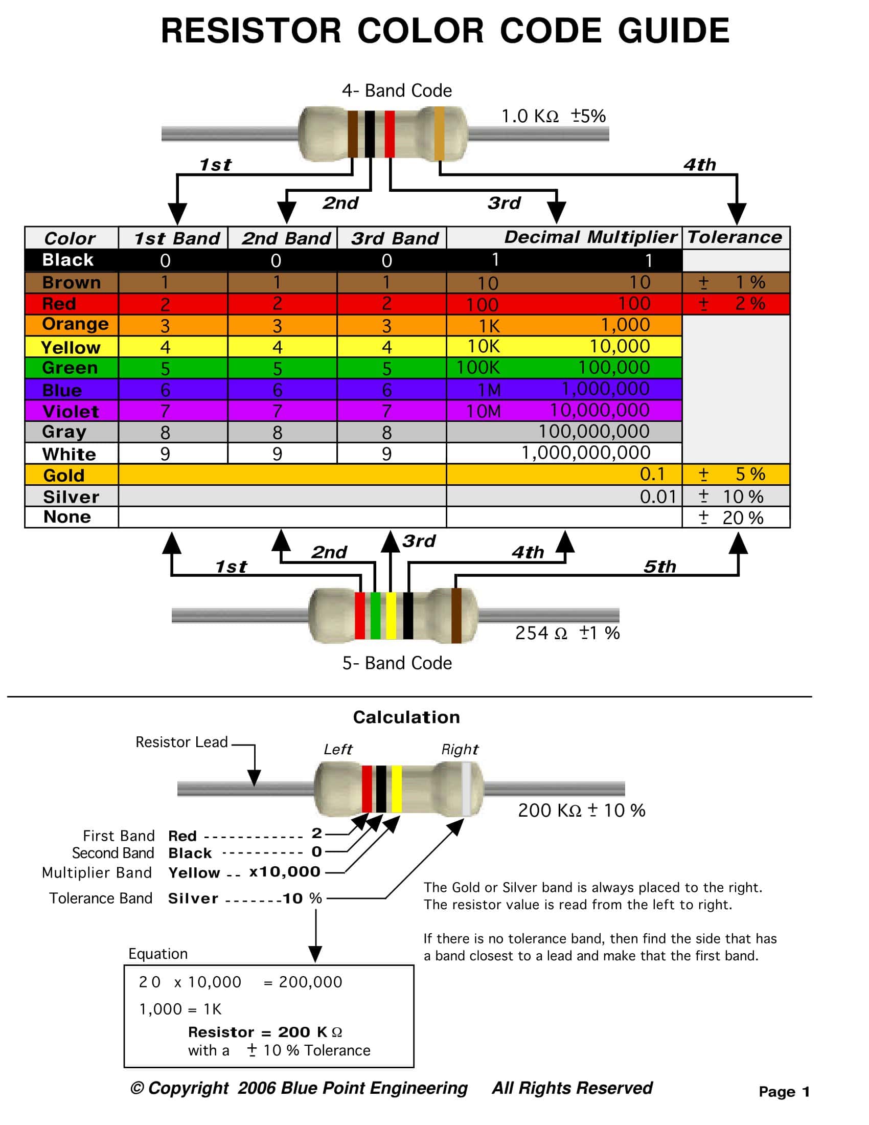
Resistors can have between three and six bands, but the most common types have either four or five.
- Four-band Resistors:
- 1st band: First significant figure
- 2nd band: Second significant figure
- 3rd band: Multiplier (Power of 10)
- 4th band: Tolerance
- Five-band Resistors:
- 1st band: First significant figure
- 2nd band: Second significant figure
- 3rd band: Third significant figure
- 4th band: Multiplier (Power of 10)
- 5th band: Tolerance
For example, consider a resistor with the color sequence: Red, Violet, Brown, Gold.
- Red: 2
- Violet: 7
- Brown: Multiplier of 10 (which is 10^1 = 10)
- Gold: ±5% tolerance
Multiply the two significant figures (27) by the multiplier (10), yielding a resistance of 270 ohms. The gold band indicates a tolerance of ±5%, which means the actual resistance could be within 5% above or below 270 ohms.
Tolerance Colors
- Gold – ±5%
- Silver – ±10%
- No color – ±20%
Note: Some resistors might have additional bands for reliability or temperature coefficient, but those are less common in general-purpose applications.
Why Color Coding?
You might wonder why such a system exists instead of simply printing the resistance value onto the resistor. The primary reason is size. Many resistors are tiny, and it would be challenging to print a legible number on them. Additionally, color codes can be identified from multiple angles and in varying lighting conditions. Over time, this system became standardized, allowing for quick and efficient identification of resistors by technicians and engineers worldwide.
Tips for Remembering the Code
Many people remember the color sequence using mnemonics. A common one is: “Bad Beer Rots Our Young Guts, But Vodka Goes Well.”
Each word’s first letter corresponds to a color: Black, Brown, Red, Orange, Yellow, Green, Blue, Violet, Gray, and White.
In Summary
The resistor color code system provides a standardized way to communicate resistance values, tolerances, and other attributes in a compact and easily recognizable format. While it may seem daunting at first, with practice, reading these color codes becomes second nature.
Resistor Color Code Chart
Color | Value | Multiplier | Tolerance | Temperature Coefficient | |||
4 Band | 5 Band | 6 Band | 4, 5 & 6 Band | ||||
Black | 0 | 0 | 0 | x1 | 250 ppm/°C | ||
Brown | 1 | 1 | 1 | x10 | ±1% | 100 ppm/°C | |
Red | 2 | 2 | 2 | x100 | ±2% | 50 ppm/°C | |
Orange | 3 | 3 | 3 | x1k | 15 ppm/°C | ||
Yellow | 4 | 4 | 4 | x10k | 25 ppm/°C | ||
Green | 5 | 5 | 5 | x100k | ±0.5% | ||
Blue | 6 | 6 | 6 | x1M | ±0.25% | 10 ppm/°C | |
Violet | 7 | 7 | 7 | x10M | ±0.1% | 5 ppm/°C | |
Gray | 8 | 8 | 8 | ±0.05% | |||
White | 9 | 9 | 9 | ||||
Gold | x0.1 | ±5% | |||||
Silver | x0.01 | ±10% | |||||
None | ±20% |
How to Use the Resistor Color Code Chart?
The Resistor Color Code Chart is a tool that aids in decoding the color bands on resistors to determine their resistance value, tolerance, and sometimes other parameters. To use the chart effectively, follow these steps:
1. Determine the Number of Bands:
- Three-band Resistors: Rare but exist. Two bands for value and one for the multiplier.
- Four-band Resistors: Most common. Two bands for value, one for the multiplier, and one for tolerance.
- Five-band Resistors: Three bands for value, one for the multiplier, and one for tolerance.
- Six-band Resistors: Three bands for value, one for the multiplier, one for tolerance, and one for temperature coefficient.
2. Identify the Colors on the Resistor:
Hold the resistor such that the band closest to one end starts as the first band. This will usually be a color other than gold or silver. The bands should be read from left to right.
3. Refer to the Basic Color Codes:
Here’s a quick refresher on the basic color codes:
- Black – 0
- Brown – 1
- Red – 2
- Orange – 3
- Yellow – 4
- Green – 5
- Blue – 6
- Violet (or Purple) – 7
- Gray – 8
- White – 9
4. Decode the Bands:
For a Four-band Resistor:
- 1st band: First significant figure
- 2nd band: Second significant figure
- 3rd band: Multiplier (Power of 10)
- 4th band: Tolerance (often Gold, Silver, or absent)
For a Five-band Resistor:
- 1st band: First significant figure
- 2nd band: Second significant figure
- 3rd band: Third significant figure
- 4th band: Multiplier (Power of 10)
- 5th band: Tolerance
5. Calculate the Resistance Value:
Using the decoded figures and the multiplier, calculate the resistance. For instance, if you have the bands Red (2), Violet (7), and Brown (multiplier of 10), the resistance would be 27 multiplied by 10 = 270 ohms.
6. Determine the Tolerance:
For the fourth (or fifth) band:
- Gold – ±5%
- Silver – ±10%
- No color – ±20%
This indicates the range within which the actual resistance may lie. For instance, a 270 ohm resistor with a gold band can have a value between 270−0.05×270270−0.05×270 and 270+0.05×270270+0.05×270.
7. (Optional) Determine the Temperature Coefficient:
This is typically for six-band resistors. It tells how much the resistance will change with a change in temperature. This is generally of interest in precision or high-reliability applications.
Tips:
- Ensure good lighting when determining the color of the bands. Some colors, especially between blue, violet, and gray, can be hard to distinguish.
- If you’re new to this, practice with a set of resistors and double-check your results using a digital multimeter. This will help solidify your understanding and improve your accuracy.
Types of Resistors
- Fixed Resistors: These resistors have a fixed resistance value and are the most common type.
- Variable Resistors: Their resistance can be adjusted. They include:
- Potentiometers: Used to adjust signal levels, position sensors, etc.
- Rheostats: Typically used to control current.
- Special Resistors:
- Thermistors: The resistance varies with temperature. Used in temperature sensing.
- Photoresistors (LDR): Resistance changes with light intensity.
- Varistors: Resistance varies with voltage. Used for overvoltage protection.
- Resistor Networks: Multiple resistors packaged together, often in a single package.
- Power Resistors: Designed to handle higher power. They come in larger packages and often have metal or ceramic cases for better heat dissipation.
Additional Codes and Markings
- Surface Mount Device (SMD) Codes: For SMD resistors, space is limited, so a numerical code is used. For instance, “103” denotes a resistor with a value of 10 x 10^3 = 10,000 ohms or 10k ohms.
- Power Rating: Some resistors have their power rating printed on them. Common power ratings for small, through-hole resistors are 1/4W, 1/2W, 1W, etc. The power rating indicates the maximum power the resistor can safely dissipate.
- Tolerance: Beyond color bands, some high-precision resistors have their tolerance printed as a percentage.
- Temperature Coefficient: This specifies how much the resistance value will change with a temperature change. It’s often given in ppm/°C (parts per million per degree Celsius). For instance, a coefficient of 100 ppm/°C means the resistance can change by 100 ohms for every million ohms of resistance per degree Celsius temperature change.
- Reliability or Failure Rate: Some military-grade or high-reliability resistors have a color band denoting their failure rate, usually given in percentage or failures per million hours of operation.
- Manufacturer’s Mark: Some resistors may carry a logo or mark of the manufacturer.
- Materials and Construction: While not always directly marked, the type of material and construction can sometimes be inferred from the resistor’s appearance:
- Carbon Composition: Made of a mixture of carbon powder and a binder. They’re generally cylindrical with a rough texture.
- Metal Film or Carbon Film: Made by depositing a thin metal or carbon layer onto a ceramic rod.
- Wirewound: Consist of a metal wire wrapped around a ceramic or fiberglass core. Used for high-power applications.
- Metal Oxide: Made using metal oxide films. They offer better stability and tolerance compared to carbon composition resistors.
Resistor Color Code : Calculation with Different Examples
A resistor color code calculator is a tool that helps you determine the resistance value of a resistor based on its color bands without having to remember the color code chart. These calculators can be found online, in mobile apps, or even as physical wheel charts. Now, let’s understand how the calculator works in a friendly manner.
For a Four-band Resistor:
1. Identify the first color band. This gives you the first number.
2. Identify the second color band. This gives you the second number.
3. The third color band tells you what to multiply the two numbers by. Think of this as adding zeroes.
4. The fourth color band tells you the range (or “wiggle room”) around the number you got. This is often described as tolerance.
Friendly Formula:
First Color Number followed by Second Color Number with the number of zeroes determined by the Third Color. Consider the range (or “wiggle room”) based on the Fourth Color.
For a Five-band Resistor:
1. Identify the first color band. This gives you the first number.
2. Identify the second color band. This gives you the second number.
3. Identify the third color band. This gives you the third number.
4. The fourth color band tells you what to multiply the three numbers by. Again, think of this as adding zeroes.
5. The fifth color band gives you the range (or “wiggle room”) around the number you got.
Friendly Formula:
First Color Number followed by Second Color Number and then the Third Color Number, with the number of zeroes determined by the Fourth Color. Consider the range (or “wiggle room”) based on the Fifth Color.
Example in Simple Words (Four-band Resistor):
Say you have a resistor with the colors: Red, Violet, Brown, and Gold.
1. Red means 2. 2. Violet means 7. 3. Brown means we add one zero.
So, put it together: 27 with one zero is 270.
4. Gold means there’s a little “wiggle room” around that 270. Specifically, the actual resistance might be 5% higher or lower.
So, our friendly calculator tells us: The resistor is about 270 ohms, but it could be 5% more or less than that.
Conclusion
With the printable PDF and Word resistor color code charts provided in this guide, you now have helpful references to keep your projects running smoothly. No more scratching your head trying to decode colored bands – just consult your chart! Whether you need a 4-band, 5-band, or 6-band chart, these free resources have you covered. Print out a few copies to keep by your workspace, in your tool kit, or wherever you tend to work.
Having the color codes for resistors at your fingertips ensures accuracy and efficiency. The next time you encounter resistors with cryptic colored bands, you can confidently look up the values. Our charts take the guesswork out of decoding even the most complex resistor color codes. Use them as a training guide or an ever-ready reference. Feel free to revisit this collection anytime you need a refresh on resistor color codes. Now you have the tools to work safely, efficiently, and confidently on your next electronics project.
FAQs
How many color bands can a resistor have?
Resistors can have between three and six bands. Most common types have four or five bands. The number of bands helps determine the precision and sometimes other attributes of the resistor.
I see a resistor without a tolerance band. What does that mean?
If a resistor does not have a tolerance band, it typically means the tolerance is ±20%.
Do SMD (Surface Mount Device) resistors also have color codes?
Typically, no. SMD resistors often use a numerical code system because of their tiny size. The first few numbers indicate the significant figures, and the last number is the multiplier.
What if I mix up the direction of reading the bands?
The first band is usually closer to one end than the other. Additionally, the last band (indicating tolerance) is often gold, silver, or a distinct color, helping indicate the reading direction. However, in the absence of such cues, the resistor value may be misinterpreted.
What if the colors on the resistor have faded?
If the colors are not distinguishable, it’s best to measure the resistor with a multimeter or replace it with a known resistor.
How do I differentiate between a four-band and a five-band resistor if both have similar colors?
The gap between bands is usually a good indication. A wider gap before the last band on a five-band resistor typically differentiates it from a four-band resistor.