Conduit Fill Chart is an essential tool in electrical installations, ensuring that conduit systems are properly sized for the cables they contain. This comprehensive guide will walk you through the basics of understanding and interpreting a Conduit Fill Chart, as well as provide guidelines for safe and effective conduit installation. If you’re dealing with common conduit sizing issues, we’ll also explore troubleshooting solutions to help you navigate through any challenges.
Table of Contents
What is the Conduit Fill Chart?

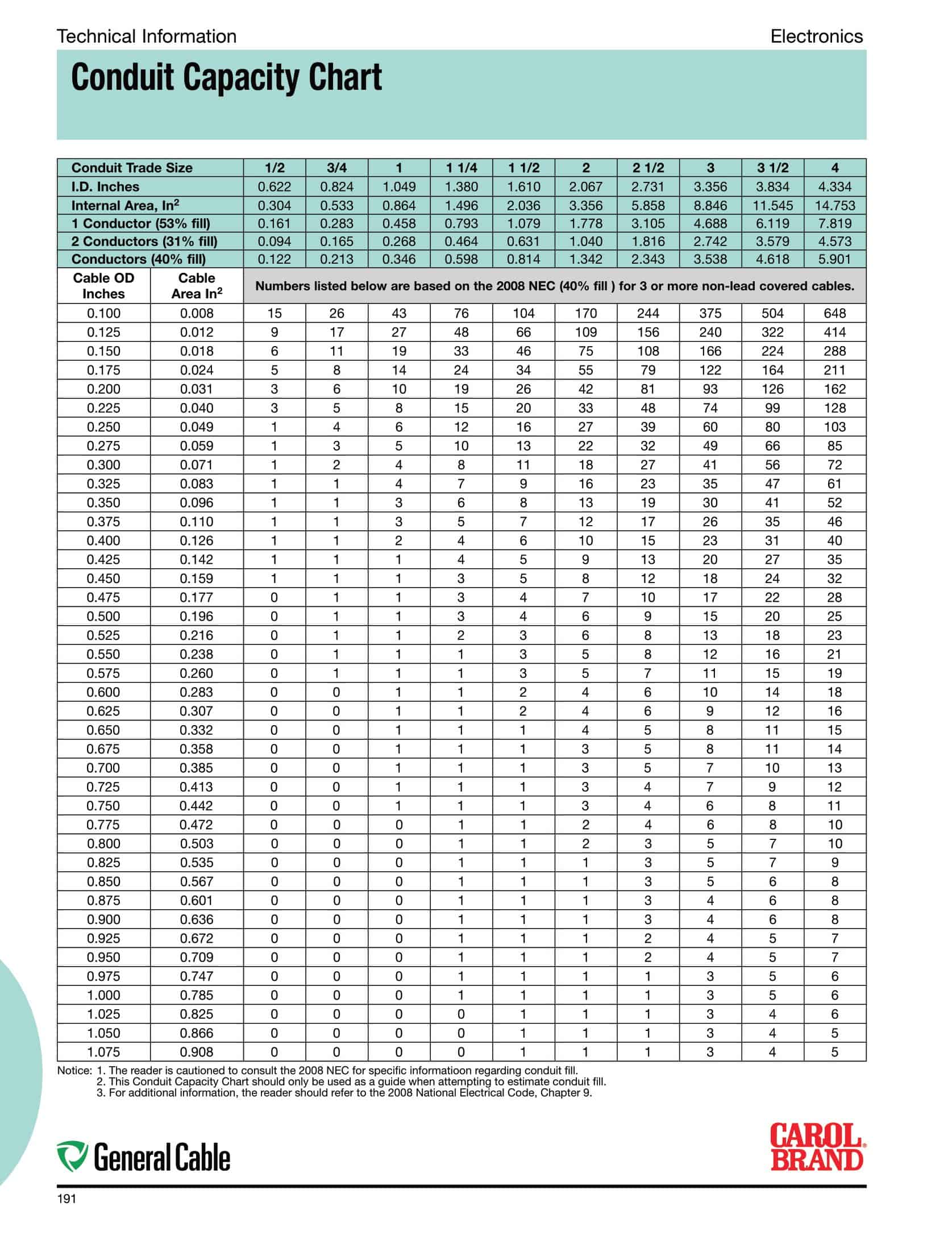
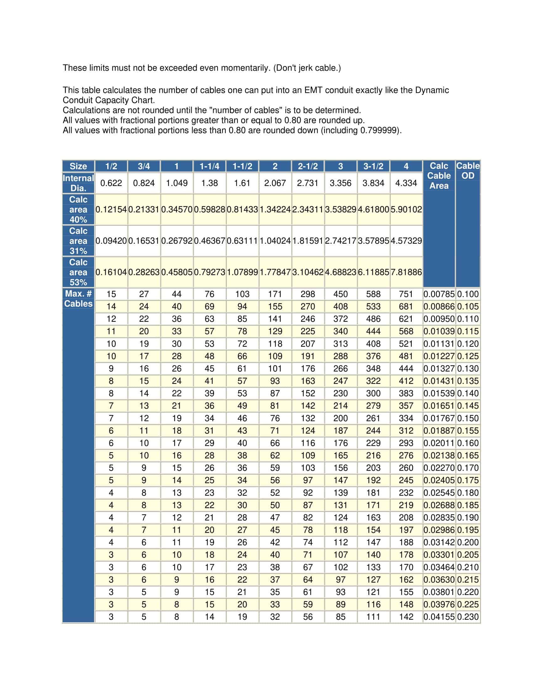
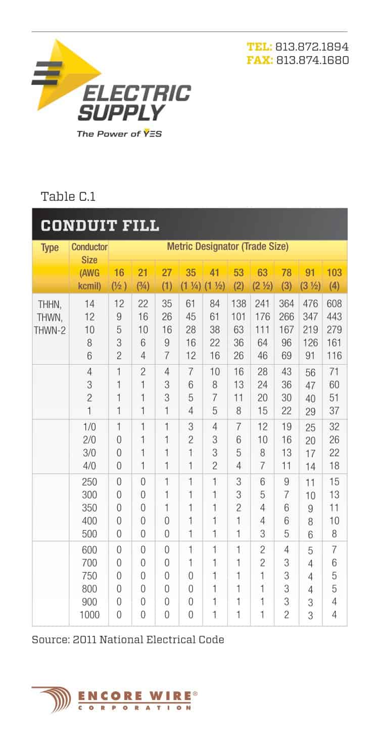
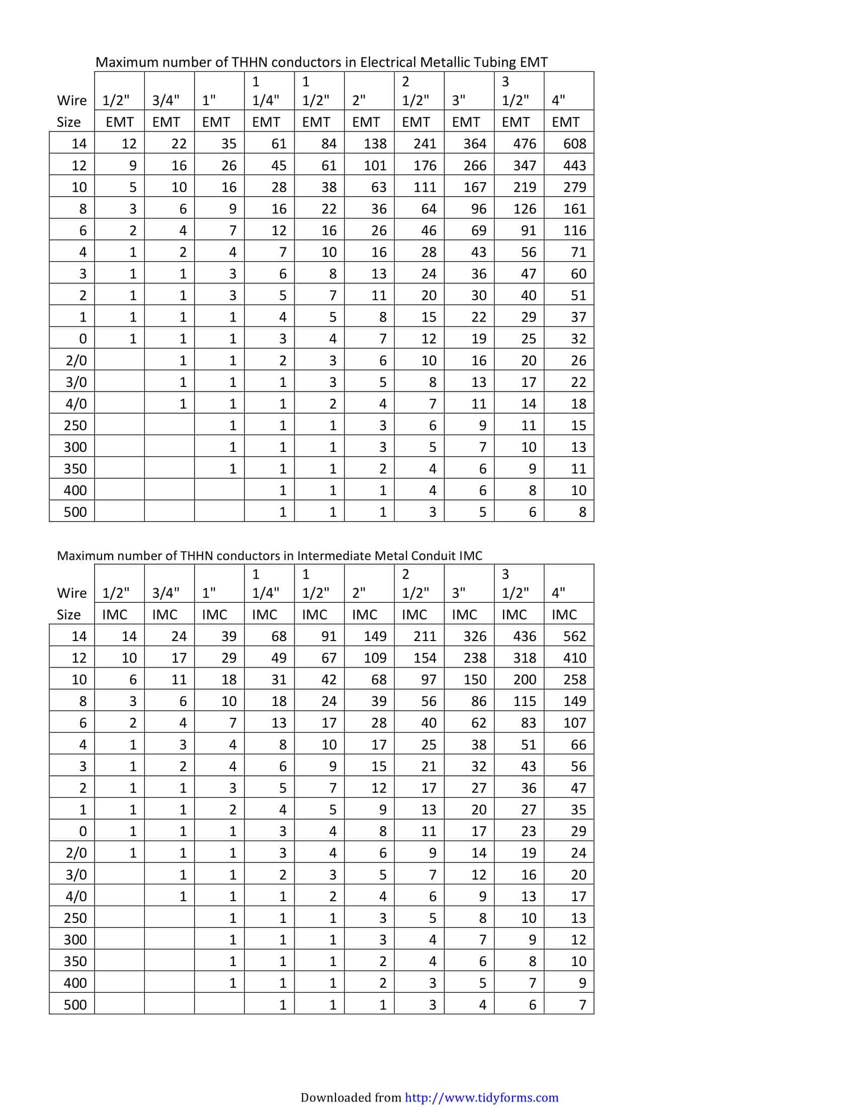
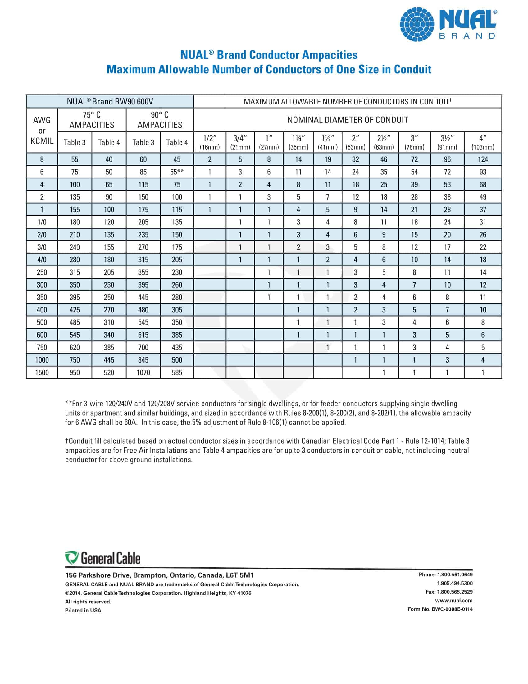
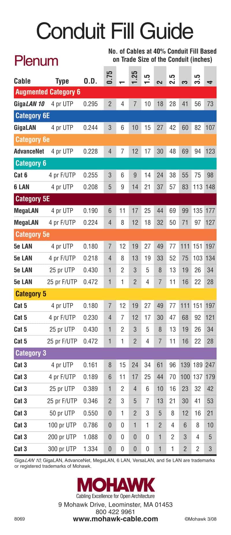
It is a reference chart that provides information on the maximum number and size of cables that can be placed in different types and sizes of conduits. By using this chart, you can determine the appropriate conduit size for a given set of cables. The proper sizing of conduits is crucial to ensure that cables can be easily pulled through without damaging them or causing excessive heat buildup.
Importance of Proper Conduit Sizing: Why is it so important to adhere to the conduit fill requirements? Well, simply put, improper conduit sizing can lead to serious safety hazards and installation issues. Overfilled conduits can put excessive strain on the cables, leading to insulation damage, increased resistance, and even fire hazards. On the other hand, undersized conduits can make cable installation difficult and time-consuming, potentially damaging the cables in the process.
Let’s delve deeper into the importance of proper conduit sizing. When it comes to electrical installations, safety should always be the top priority. Overfilled conduits not only strain the cables but also restrict the flow of air around them. This lack of ventilation can cause the cables to overheat, leading to insulation breakdown and, in extreme cases, fire. By adhering to the conduit fill requirements, you can ensure that the cables have enough space to dissipate heat effectively, reducing the risk of overheating and potential fire hazards.
Furthermore, undersized conduits can create a host of installation challenges. Imagine trying to thread a thick cable through a narrow conduit. It would be like trying to fit a square peg into a round hole. Not only would it be time-consuming, but it could also damage the cable’s insulation or even break the cable itself. By using the conduit fill chart to select the appropriate conduit size, you can ensure a smooth and efficient installation process, minimizing the risk of cable damage and saving valuable time and resources.
Conduit Fill Chart Printable
Key Components of a Conduit Fill Chart

When it comes to understanding a Conduit Fill Chart, there are two main components that play a crucial role: the types of conduits and the conduit sizes and capacities. Let’s dive deeper into each of these components to gain a more comprehensive understanding.
Types of Conduits
Conduits, like the veins that carry life-sustaining blood throughout our bodies, come in various materials and forms. These materials include metal, such as rigid metal conduit or intermediate metal conduit, and non-metal, such as PVC or HDPE. Each type of conduit possesses its own unique characteristics and limitations that must be carefully considered.
For instance, metal conduits offer excellent mechanical strength and durability, making them ideal for applications that require protection against physical damage. On the other hand, non-metal conduits, like PVC, provide exceptional corrosion resistance and are often favored in environments where moisture and chemicals are a concern.
Furthermore, it is important to note that different types of conduits have varying temperature ranges within which they can operate effectively. Some conduits can withstand extreme temperatures, while others may have limitations. Therefore, selecting the appropriate type of conduit based on the specific application requirements is paramount to ensuring a safe and reliable electrical system.
Conduit Sizes and Capacities
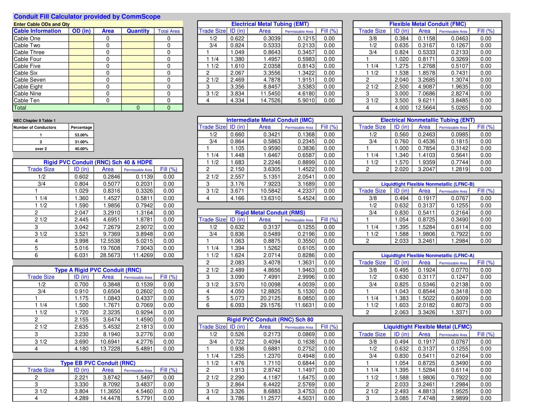
Now that we have explored the different types of conduits, let’s shift our focus to the conduit sizes and capacities, which are denoted by their nominal diameter or trade size. However, it is important to keep in mind that the actual inside diameter may vary depending on the conduit material.
The Conduit Fill Chart, like a trusted guide, provides valuable information on the maximum number and size of cables that can be safely installed in each conduit size. This information is crucial for electrical engineers and installers to ensure compliance with industry standards and regulations.
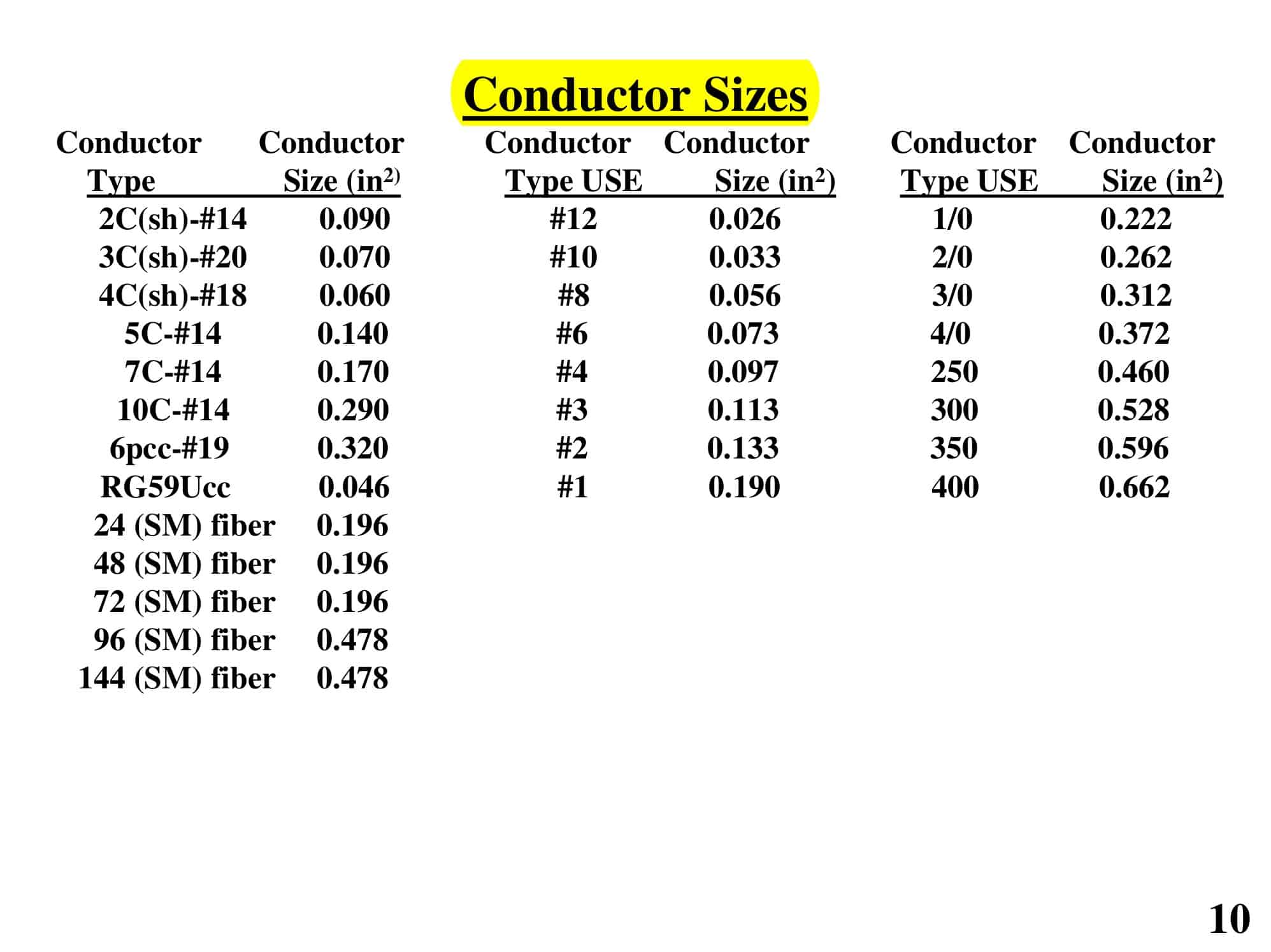
When considering conduit sizes and capacities, it is essential to take into account various factors. These factors include the diameter of the cables, the thickness of their insulation, and the fill ratio, which determines the percentage of the conduit’s cross-sectional area that can be occupied by the cables. By carefully considering these factors, one can ensure that the conduit is not overcrowded, which could lead to overheating and potential hazards.
Additionally, it is worth noting that the Conduit Fill Chart provides guidance on the different types of cables that can be safely installed in each conduit size. This information is invaluable as it helps prevent issues such as cable damage, signal interference, and excessive voltage drop.
So, whether you are an electrical professional or a curious enthusiast, understanding the key components of a Conduit Fill Chart is essential. By delving into the types of conduits and the conduit sizes and capacities, you can navigate the intricate world of conduit systems with confidence and ensure the safe and efficient flow of electrical power.
Reading and Interpreting a Conduit Fill Chart
Now that we understand the basic components of a Conduit Fill Chart, let’s explore how to read and interpret the information presented.
When it comes to deciphering symbols and abbreviations on a Conduit Fill Chart, it’s crucial to familiarize yourself with these indicators to accurately interpret the chart. These symbols and abbreviations provide additional information about specific conditions or requirements. For example, you may come across arrows indicating cable orientation, which can be helpful in ensuring proper cable installation. Additionally, asterisks may denote special conditions that need to be taken into consideration, such as cable bundling or specific temperature ratings. Another common symbol you may encounter is dashed lines, which represent derating factors. These factors are essential in determining the maximum number of cables that can be safely installed in a conduit based on factors such as ambient temperature.
Calculating Conduit Fill Percentages
Conduit fill percentages play a vital role in determining the appropriate conduit size based on the number and size of cables being installed. To calculate the fill percentage, you need to divide the total cable area by the internal area of the conduit and then multiply by 100. This calculation ensures that you have enough space within the conduit to accommodate the cables without exceeding the maximum fill percentage specified in the Conduit Fill Chart. It’s important to note that exceeding the recommended fill percentage can lead to issues such as overheating, signal interference, and difficulty in future cable installations or replacements. Therefore, adhering to the fill percentage guidelines outlined in the chart is crucial for safe and efficient cable installation.
When calculating conduit fill percentages, it’s essential to consider the various factors that can affect the fill capacity. Factors such as cable diameter, insulation thickness, and the presence of multiple cables within the conduit can all impact the fill percentage. Additionally, you may need to take into account any future expansion plans or the potential need for additional cables in the conduit. By carefully considering these factors and accurately calculating the fill percentage, you can ensure that your cable installation meets the necessary requirements for optimal performance and safety.
Guidelines for Safe and Effective Conduit Installation
When installing conduits, it’s crucial to adhere to the guidelines set forth by the National Electrical Code (NEC) and follow safety precautions to ensure a reliable and compliant electrical installation.
National Electrical Code (NEC) Standards
The NEC provides a comprehensive set of standards and guidelines for electrical installations to promote safety and mitigate hazards. These standards cover various aspects, including conduit sizing, installation methods, grounding requirements, and more. Familiarize yourself with the relevant NEC sections to ensure proper compliance and avoid costly rework or safety issues.
For example, NEC Article 300.4(D) specifies that conduits must be securely fastened in place to prevent movement or damage. This ensures that the conduits remain in their intended position and do not pose a risk to the electrical system. By following this standard, you can ensure the longevity and reliability of your conduit installation.
Safety Precautions for Conduit Installation
Installing conduits can involve working with live electrical equipment and potentially hazardous environments. Always prioritize safety by wearing appropriate personal protective equipment (PPE) such as gloves, safety glasses, and insulated tools. Additionally, ensure that all power sources are properly de-energized before starting any installation work. Regularly inspect conduits for any signs of damage or degradation, and promptly address any issues to maintain a safe working environment.
Furthermore, it is important to consider the environmental conditions in which the conduits will be installed. For example, if the conduits are being installed in an area with high humidity or corrosive substances, it may be necessary to use corrosion-resistant materials or coatings to prevent premature deterioration. By taking these additional precautions, you can ensure the longevity and reliability of your conduit installation, even in challenging environments.
Troubleshooting Common Conduit Sizing Issues
Despite careful planning, conduit sizing issues can still arise during installations. Let’s explore some common challenges and their corresponding solutions.
Overfilled Conduits: Risks and Solutions
When a conduit is overfilled beyond the recommended fill percentage, it can lead to cable damage, increased resistance, and excessive heat buildup. This can result in reduced efficiency and potential hazards. To tackle this issue, consider upsizing the conduit to accommodate the additional cables or reducing the number of cables being installed. By providing sufficient space within the conduit, you can ensure proper cable performance and minimize the risk of overheating. Additionally, you can explore alternative conduit materials with larger internal diameters or employ techniques such as grouping smaller cables together, which can help optimize the use of available space.
Furthermore, it is important to consider the future expansion needs of the electrical system when determining conduit size. By anticipating potential growth and allowing for additional cables, you can avoid the need for costly and disruptive modifications in the future. Planning ahead and considering the long-term requirements of the installation can save both time and resources.
Dealing with Undersized Conduits
Undersized conduits can make cable installation challenging and may require excessive force, potentially damaging the cables or compromising their insulation. In such cases, it is crucial to address the issue promptly to ensure the integrity and safety of the electrical system. Consider replacing the undersized conduit with a larger size that can accommodate the cables comfortably. This will not only make the installation process smoother but also reduce the risk of cable damage.
In situations where replacing the conduit is not feasible, alternative routing methods can be employed to minimize cable stress. By carefully planning the cable paths and avoiding sharp bends or excessive pulling tensions, you can protect the cables from unnecessary strain and prevent insulation degradation. It is essential to prioritize the long-term performance and reliability of the electrical system by implementing proper cable management practices.
In conclusion, a Conduit Fill Chart is a valuable tool in determining the proper sizing of conduits for electrical installations. By understanding the basics, reading and interpreting the chart correctly, and following guidelines outlined by the NEC, you can ensure safe and effective conduit installation. Should common conduit sizing issues arise, troubleshooting techniques and solutions can help navigate through challenges. Always prioritize safety and compliance, and consult experts or electrical professionals when in doubt.
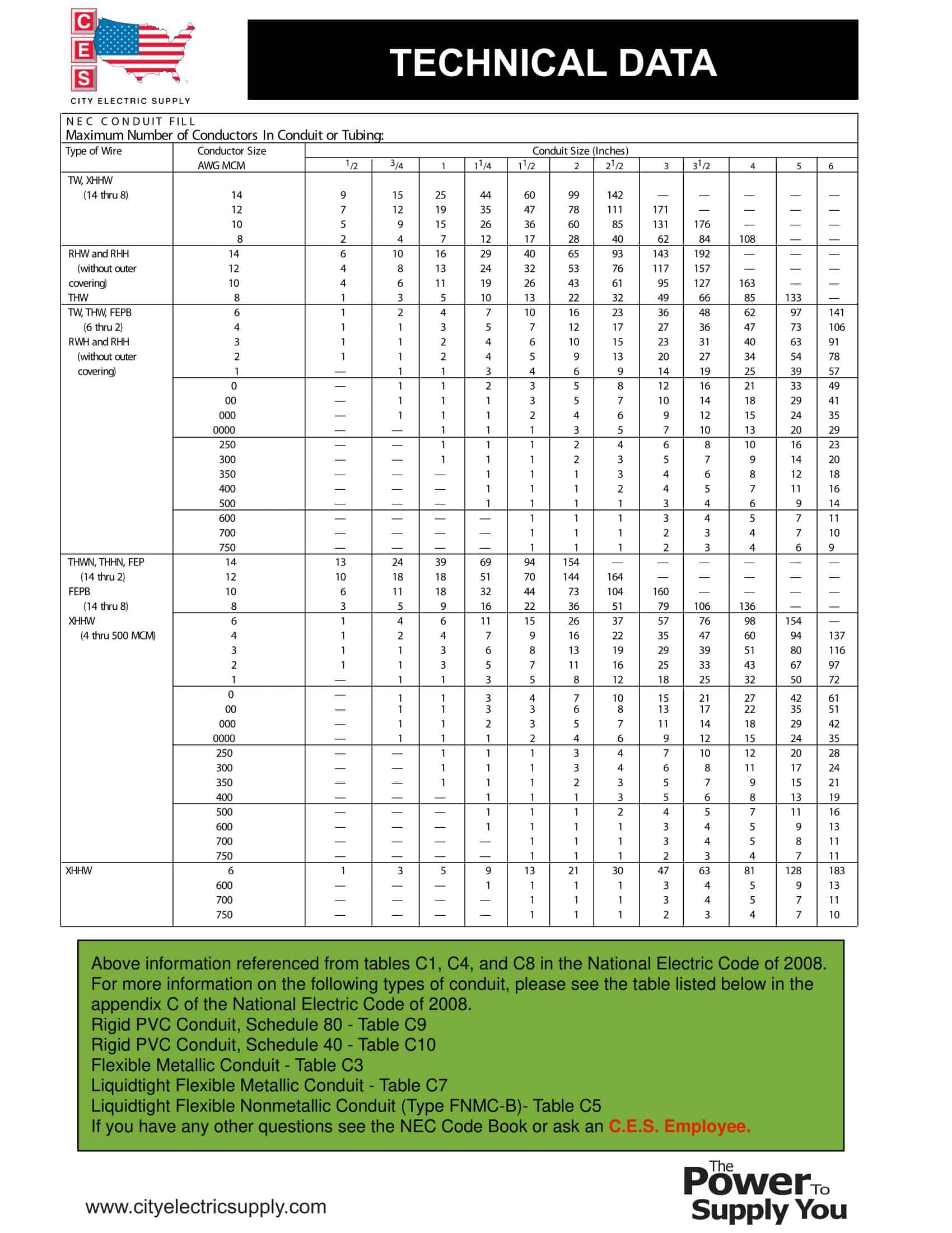
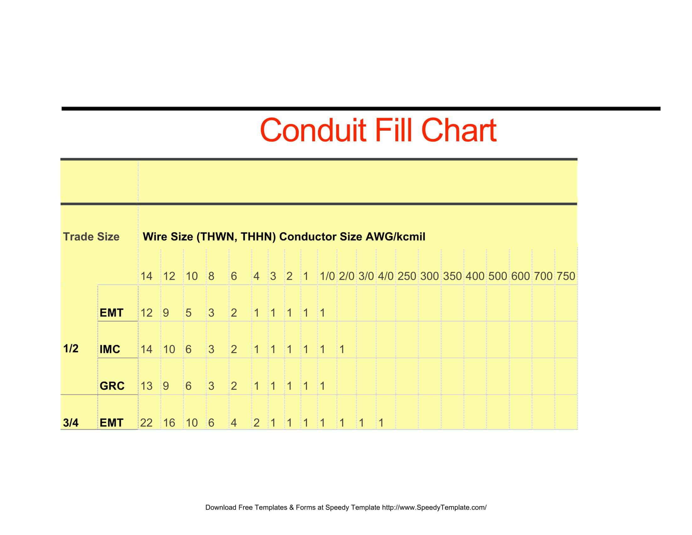
Conduit Fill Charts
| Trade Size | Conductor Size AWG/kcmil. For Cable Type | (THWN, THHN] | |||||||||||||||||||||
| 14 | 12 | 10 | 8 | 6 | 4 | 3 | 2 | 1 | 1/0 | 2/0 | 3/0 | 4/0 | 250 | 300 | 350 | 400 | 500 | 600 | 700 | 750 | |||
| 1/2 | EMT | 12 | 9 | 5 | 3 | 2 | 1 | 1 | 1 | 1 | 1 | ||||||||||||
| IMC | 14 | 10 | 6 | 3 | 2 | 1 | 1 | 1 | 1 | 1 | 1 | ||||||||||||
| GRC | 13 | 9 | 6 | 3 | 2 | 1 | 1 | 1 | 1 | 1 | |||||||||||||
| 3/4 | EMT | 22 | 16 | 10 | 6 | 4 | 2 | 1 | 1 | 1 | 1 | 1 | 1 | 1 | |||||||||
| IMC | 24 | 17 | 11 | 6 | 4 | 3 | 2 | 1 | 1 | 1 | 1 | 1 | 1 | ||||||||||
| GRC | 22 | 16 | 10 | 6 | 4 | 2 | 1 | 1 | 1 | 1 | 1 | 1 | 1 | ||||||||||
| 1 | EMT | 35 | 26 | 16 | 9 | 7 | 4 | 3 | 3 | 1 | 1 | 1 | 1 | 1 | 1 | 1 | 1 | ||||||
| IMC | 39 | 29 | 18 | 10 | 7 | 4 | 4 | 3 | 2 | 1 | 1 | 1 | 1 | 1 | 1 | 1 | 1 | ||||||
| GRC | 36 | 26 | 17 | 9 | 7 | 4 | 3 | 3 | 1 | 1 | 1 | 1 | 1 | 1 | 1 | 1 | 1 | ||||||
| 11/4 | EMT | 61 | 45 | 28 | 16 | 12 | 7 | 6 | 5 | 4 | 3 | 2 | 1 | 1 | 1 | 1 | 1 | 1 | 1 | 1 | 1 | ||
| IMC | 68 | 49 | 31 | 18 | 13 | 8 | 6 | 5 | 4 | 3 | 2 | 1 | 1 | 1 | 1 | 1 | 1 | 1 | 1 | 1 | 1 | ||
| GRC | 63 | 46 | 29 | 16 | 12 | 7 | 6 | 5 | 4 | 3 | 2 | 1 | 1 | 1 | 1 | 1 | 1 | 1 | 1 | 1 | |||
| 11/2 | EMT | 84 | 61 | 38 | 22 | 16 | 10 | 8 | 7 | 5 | 4 | 3 | 2 | 1 | 1 | 1 | 1 | 1 | 1 | 1 | 1 | 1 | |
| IMC | 91 | 67 | 42 | 24 | 17 | 10 | 9 | 7 | 5 | 4 | 4 | 3 | 3 | 2 | 1 | 1 | 1 | 1 | 1 | 1 | 1 | ||
| GRC | 85 | 62 | 39 | 22 | 16 | 10 | 8 | 7 | 5 | 4 | 3 | 3 | 2 | 1 | 1 | 1 | 1 | 1 | 1 | 1 | 1 | ||
| 2 | EMT | 138 | 101 | 63 | 36 | 26 | 16 | 13 | 11 | 8 | 7 | 6 | 5 | 4 | 3 | 2 | 1 | 1 | 1 | 1 | 1 | 1 | |
| IMC | 149 | 109 | 68 | 39 | 38 | 17 | 15 | 12 | 9 | 8 | 6 | 5 | 4 | 3 | 3 | 2 | 2 | 1 | 1 | 1 | 1 | ||
| GRC | 140 | 102 | 64 | 37 | 27 | 16 | 14 | 11 | 8 | 7 | 6 | 5 | 4 | 3 | 3 | 2 | 2 | 1 | 1 | 1 | 1 | ||
| 2 1/5 | EMT | 241 | 176 | 111 | 64 | 46 | 28 | 24 | 20 | 15 | 12 | 10 | 8 | 7 | 6 | 5 | 4 | 4 | 3 | 2 | 2 | 1 | |
| IMC | 211 | 154 | 97 | 56 | 40 | 25 | 21 | 17 | 13 | 11 | 9 | 7 | 6 | 5 | 4 | 4 | 3 | 3 | 2 | 1 | 1 | ||
| GRC | 200 | 146 | 92 | 53 | 38 | 23 | 20 | 17 | 12 | 10 | 8 | 7 | 6 | 5 | 4 | 3 | 3 | 2 | 1 | 1 | 1 | ||
| 3 | EMT | 364 | 266 | 167 | 96 | 69 | 43 | 36 | 30 | 22 | 19 | 16 | 13 | 11 | 9 | 7 | 6 | 6 | 5 | 4 | 3 | 3 | |
| IMC | 362 | 238 | 150 | 86 | 62 | 38 | 32 | 27 | 20 | 17 | 14 | 12 | 9 | 8 | 7 | 6 | 5 | 4 | 3 | 3 | 3 | ||
| GRC | 309 | 225 | 142 | 82 | 59 | 36 | 31 | 26 | 19 | 16 | 13 | 11 | 9 | 7 | 6 | 5 | 5 | 4 | 3 | 3 | 3 | ||
| 3 1/5 | EMT | 476 | 347 | 219 | 126 | 91 | 56 | 47 | 40 | 29 | 25 | 20 | 17 | 14 | 11 | 10 | 9 | 8 | 6 | 5 | 4 | 4 | |
| IMC | 436 | 318 | 200 | 115 | 83 | 51 | 43 | 36 | 27 | 23 | 19 | 16 | 13 | 10 | 9 | 8 | 7 | 6 | 5 | 4 | 4 | ||
| GRC | 412 | 301 | 189 | 109 | 79 | 48 | 41 | 34 | 25 | 21 | 18 | 15 | 12 | 10 | 8 | 7 | 7 | 5 | 4 | 4 | 4 | ||
| 4 | EMT | 608 | 443 | 279 | 161 | 116 | 71 | 60 | 51 | 37 | 32 | 26 | 22 | 18 | 15 | 13 | 11 | 10 | 8 | 7 | 6 | 5 | |
| IMC | 562 | 410 | 258 | 149 | 107 | 66 | 56 | 47 | 35 | 29 | 24 | 20 | 17 | 13 | 12 | 10 | 9 | 7 | 6 | 5 | 5 | ||
| GRC | 531 | 387 | 244 | 140 | 101 | 62 | 53 | 44 | 33 | 27 | 23 | 19 | 16 | 13 | 11 | 10 | 8 | 7 | 6 | 5 | 5 | ||
FAQs
What is the maximum fill percentage?
The National Electrical Code (NEC) typically limits fill to 40% for three or more conductors in a conduit. However, there are variations, like a 60% fill limit for one conductor and a 30% fill limit for two conductors.
Does the type of wire insulation matter for conduit fill?
Yes, the type of wire insulation (e.g., THHN, THWN) can affect the wire’s outer diameter and thus impact the number of wires that can fit in a conduit.
Can different sized wires be in the same conduit?
Yes, conduits can contain different sized wires, but the combined total cross-sectional area of all wires should not exceed the conduit fill percentage.
Does conduit type (PVC, EMT, RMC, etc.) matter for conduit fill?
Yes, different types of conduit may have different inner diameters, affecting the number of wires they can accommodate.
How do I account for bends in the conduit?
While bends do not directly affect conduit fill calculations, they can make pulling wires more challenging. More bends may require a higher pulling force.
Is there a difference between conduit fill for power and communications cables?
Yes, communications cables like CAT5 or CAT6 typically have different diameter and construction than power cables, leading to different fill calculations.
Where can I find a conduit fill chart?
Conduit fill charts can often be found in electrical reference books, online resources, and within the National Electrical Code (NEC) guidelines.













![Free Printable Pie Chart Templates [Excel, PDF, Word] Maker 1 Pie Chart](https://www.typecalendar.com/wp-content/uploads/2023/06/Pie-Chart-150x150.jpg 150w, https://www.typecalendar.com/wp-content/uploads/2023/06/Pie-Chart-1200x1200.jpg 1200w)
![Free Printable Reward Chart Templates [Word, PDF] Teachers 2 Reward Chart](https://www.typecalendar.com/wp-content/uploads/2023/03/Reward-Chart-150x150.jpg 150w, https://www.typecalendar.com/wp-content/uploads/2023/03/Reward-Chart-1200x1200.jpg 1200w)
![Free Printable Behavior Chart Templates [PDF, Word, Excel] 3 Behavior Chart](https://www.typecalendar.com/wp-content/uploads/2023/02/Behavior-Chart-150x150.jpg 150w, https://www.typecalendar.com/wp-content/uploads/2023/02/Behavior-Chart-1200x1200.jpg 1200w)
